The use of fiber optics as light guidance allows great modularity and flexibility in the setup of an optical measurement system. Optical fibers can be made of many materials, such as plastic, glass, and silicates (SiO2). For high-quality fiber optics, as used in spectroscopic applications, synthetic fused silica (amorphous silicon dioxide) is used, which can be intentionally doped with trace elements to adjust the optical properties of the glass.
Table of contents
- Basic principles
- Product codes
- Fiber optic design
- Solarization-resistant fibers for deep UV applications
- Fiber optic jacketing
- Fiber optic probe properties
- Fiber optic connectors
Basic Principles
The basic principle of light transport through an optical fiber is total internal reflection. This means that the light within the numerical aperture of a fiber (NA = input acceptance cone) will be reflected and transported through the fiber. The size of the numerical aperture depends on the materials used for the core and cladding.
We identify two basic types of silica fibers: single-mode and multi-mode fibers, depending on the propagation state of the light, traveling down the fiber. For most spectroscopic applications multi-mode fibers are used. Multi-mode fibers can be divided into 2 subcategories: step-index and graded-index. A relatively large core and high NA allow light to be easily coupled into the fiber, which allows the use of relatively inexpensive termination techniques. Step-index fibers are mainly used in spectroscopic applications.
Graded-index multimode fibers have a refractive index gradually decreasing from the core out through the cladding. Since the light travels faster in material with lower refractive index, the modal dispersion (amount of pulse-spreading) will be less.
These graded-index fibers are mainly used in telecommunication applications, where dispersion at long distances (2-15km) plays an important role.
Product Codes
A product code consists of the following attributes:
Types of Product
- FC: standard fiber-optic cable
- FCB: bifurcated fiber
- FCR: fiber-reflection probe
- FDP: fiber dip probe
Total Number of Optical Fibers
Almost any number is possible; please contact us to discuss the options available.
Wavelength Range
- UV: 200-800 nm:
- IR: 350-2500 nm:
- UVIR: 200-2500 nm:
Fibers Core Diameter
- 8 µm*
- 50 µm**
- 100 µm***
- 200 µm***
- 400 µm***
- 600 µm***
- 800 µm**
- 1000 µm**
*Only for IR fibers
**Only for UV or IR fibers
***Only for UVIR fibers
Overall Length
Expressed in meters. Almost any length is possible; please contact us to discuss the options available.
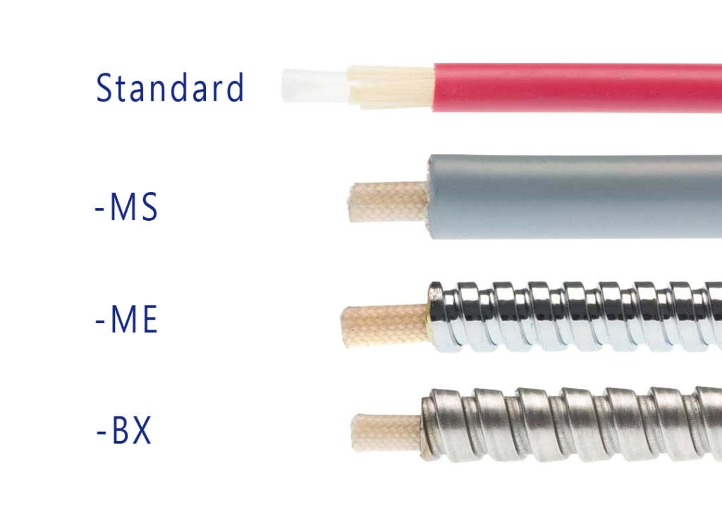
Jacketing
- Standard
- BX: stainless steel
- ME: chrome-plated brass
- MS: metal silicone
Other Options
- HT: high temperature
- HTX: extremely high temperature
- PK: PEEK:
- HY: Hastelloy®
Fiber-Optic Design
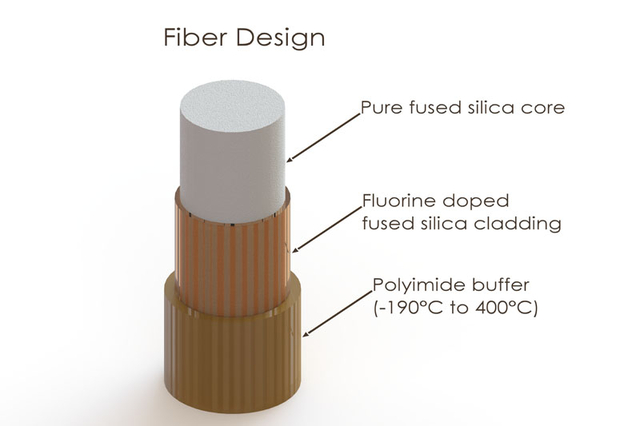
Core
Multi-mode step-index silica fibers are generally used for spectroscopic applications. They range in core thickness from 50 to 1000 microns and are made of pure silica. Other fiber cores with much higher absorption are made of certain glass types or plastics, which are not offered in this article.
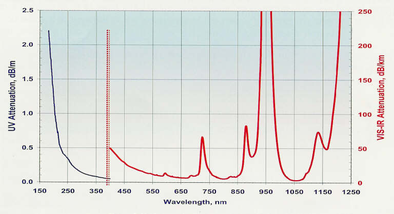
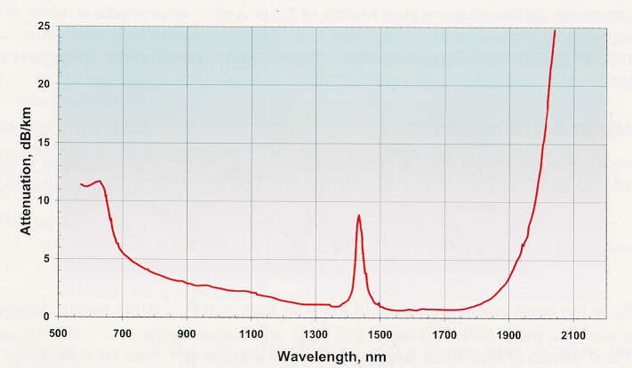
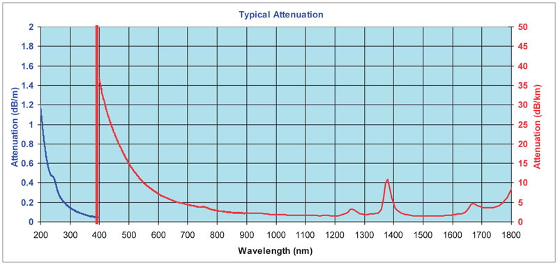
First, a distinction is made between silica with high or low OH content. Silica fibers with high OH (600-1000 PPM) are used in the UV/VIS wavelength range because of the low absorption in the UV. They are referred to as UV/VIS fibers. For Deep-UV applications (below 230 nm), special solarization-resistant fibers can be used.
The water content causes strong absorption peaks in the NIR wavelength range. In order to get good fibers for the NIR range, the ‘water’ is removed from the silica. This results in low OH fibers (<2 PPM) with low absorption in the NIR. They are referred to as VIS/NIR fibers. The best of both worlds is the so-called broadband fibers, which can be used for the UV-NIR range (200-2500 nm), the product code for these fibers is UVIR. Avantes uses this broadband type of fiber as standard.
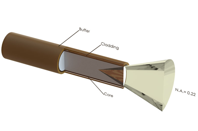
Cladding
In order to get the light-guiding effect, the core is cladded with a lower index of refraction material. For the highest-quality fibers with the lowest absorption, this is a fluorine-doped silica, the so-called silica-silica or all-silica fibers, with a numerical aperture (NA) of 0.22.
Buffers
Without further protection, fibers would easily break, because of small scratches or other irregularities on the surface. An extra layer, the buffer, is therefore added. This buffer also determines under what circumstances the fiber can be used. Temperature range, radiation, vacuum, chemical environment, and bending are factors to be considered.
Polyimide buffers offer a wide temperature range (-100 to 400°C) and superior solvent resistance. Also, this material is non-flammable. Drawbacks are sensitivity to micro bending and the difficulty to remove it.
For extreme temperatures (-270 to 700°C), metal buffers are used. Metal buffers can withstand a continuous high temperatures up to 500 °C and intermittent even up to 700°C. Low outgassing makes them also excellent for use in UHV environments.
Transmission UV/VIS Fiber-Optic Cables
Transmission VIS/NIR Fiber-Optic Cables
Transmission UV/VIS/NIR Fiber-Optic Cables
Solarization-Resistant Fibers for Deep UV Applications
Most spectroscopic applications with fiber optics have been restricted to wavelength ranges above 230 nm, because standard silica fibers with an undoped core and fluorine-doped cladding are frequently damaged by exposure to deep-UV light (below 230 nm). This solarization effect is induced by the formation of ‘color centres’ with an absorbance band of 214 nm. These color centers are formed when impurities (like Cl) exist in the core fiber material and form unbound electron pairs on the Si atom, which are affected by the deep-UV radiation.
Solarization-resistant fibers, which were hydrogen loaded, were developed for this purpose. The broadband fibers Avantes uses are Solarization-Resistant. This means that these fibers provide long-term stability at 30-40% transmission (for 215 nm). Small degradation of the transmission can still take place.
First couple of hours of these fibers show a high drop in transmission (100% to 40%). In order to have a stable transmission from the start, one can order the PRESOL option. When PRESOL is ordered with a fiber or probe Avantes pre-solarized the product for a 10-hour period, to have a constant transmission of 30-40% @ 215 nm
Solarization Normal UV400 Fiber
Solarization UVIR200 Fiber
Solarization 200 Micron UVIR Fiber
Fiber-Optic Jacketing
Avantes offers different jacketing materials for different applications. Standard fiber-optic cables and bifurcated cables are protected by Kevlar-reinforced polypropylene inner tubing with PVC red or black outer jackets. All of our standard reflection probes are protected by a flexible stainless steel jacket with an interlocking profile (BX) or a chrome-plated brass outer jacket with a hooked profile (ME) for optimum strain relief with silicon or PTFE inner tubing.
For waterproofing and some medical applications, stainless-steel spiral jacketing with Glassilk and grey outer silicon rubber coating can be provided. Inside this jacket, silicon or PTFE inner tubing is used as well. For heavy industrial environments, we advise the metal stainless steel (-BX) jacketing. It features a tensile strength of 950N. Especially for small, flexible, endoscopic probes, we use PVC rubber jacketing. Some specifics on the jacketing can be found in the technical information below. Contact us if you have any special requirements.
Fiber-Optic Probe Properties
All Avantes fiber-optic cables and probes can be modified based on customers’ requests. Most materials we use in our fiber-optic assemblies can be replaced with others to improve specific chemical or thermal resistance or to enhance vacuum or pressure properties. Please contact our fiber design engineers with your specific request.
In the following paragraphs, some of the most essential technical parameters are listed for the materials we use.
Thermal resistance
The thermal resistance of a fiber-optic assembly depends on some of the materials used:
- Fiber, the standard fiber design has a polyimide buffer, covering a wide thermal range –190 to 400 °C. For higher temperatures, metal-clad coated (to 500°C) fibers are recommended.
- Jacketing: the standard jacketing is PVC based and has a small temperature range (-20°C to 65°C). For higher temperatures, a flexible metal jacketing (-BX/ME) with silicone inner tubing (up to 250°C) or stainless steel tubing (not flexible, to 750°C) is recommended.
- Probe ends, connectors and ferrules are standard made of metal and have a wide temperature range. For special plastics, like PVC, PEEK, and Teflon, a limited temperature range is applicable.
- Bonding epoxy, the standard epoxy used is a heat-curing bonding epoxy with a temperature range of –60°C to 175°C. The curing temperature is standard 100 °C, for high-temperature ranges (order code -HT), the curing temperature is 200°C.
Chemical Resistance
The thermal resistance of a fiber-optic assembly depends on some of the materials used:
- Fiber: the standard fiber design has a polyimide buffer, which normally will not be in contact with the sample; the quartz core provides good resistance against most solvents
- Jacketing, the standard jacketing is PVC based and has a relatively good chemical resistance. The –BX stainless steel and –ME chrome plated brass jacketing also have a good chemical resistance, but are not waterproof. The Silicone metal jacketing (-MS) is recommended for waterproof environments, biomedical applications, etc. The PTFE jacketing has the best chemical resistance.
- Probe ends, connectors, and ferrules are always made of stainless steel (316) and are not very well suited to corrosive environments. For most corrosive environments PTFE or Hastelloy® C276 are recommended.
- Bonding, the standard heat-curing two-component epoxy used is resistant to water, inorganic acids and salts, alkalis and many aggressive organic solvents and most petrochemical products, and an extended range of organic and inorganic environments.
The table below gives a summary for the chemical resistance for most materials used. It has been drawn up on the basis of relevant sources in accordance with the state of the art; no claim to completeness. The data constitutes recommendations only, for which no liability can be accepted.
Please contact us if you have any doubt about the materials to use for your application.

Fiber-optic Connectors
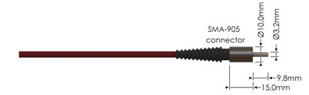
Standard SMA Connectors
We supply all of our standard fiber-optic cables, bundles, and probes with SMA-905 connectors that easily fit into our complete range of spectrometers, light sources, and accessories.
The SMA-905 connectors are screw-fitted and can be rotated over 360 degrees. The typical insertion loss for the connectors is 0.5 dB. The maximum filling diameter for bundles is 2.46mm.
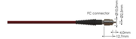
FC/PC Connectors
Optional FC/PC connectors can be mounted to our fiber-optic products. The multimode FC/PC connectors have an extremely low insertion loss of <0.2 dB. The FC/PC connector cannot rotate and always mounts into the same fixed position, and therefore has a high reproducibility.