The concept of color is one of the most fundamental building blocks on which we humans interpret the world around us. In fact, color perception is so important that children as young as 18 months old can differentiate objects by color, and by the age of three, most children can start to identify colors by name.
Therefore, it may come as a shock that most people make it all the way through their lives without ever learning the fundamentals of color science. This includes most scientists and engineers, who can make it through their entire university career without ever attending a single lecture on color science. The complexity of this seemingly straightforward topic is because color science lies at the intersection of physics, biology, and psychology.
As a result, to fully understand the subject matter, one must have a fundamental understanding of how all three of these fields are interconnected. In this application note, we are going to review the fundamentals of colorimetry by first taking a look at the structure of the human eye and how this affects our ability as humans to perceive color. After we have established how our brains process color, we will explore how color can be quantitatively measured using spectroscopy techniques using both the L*a*b color model and the CIE chromaticity diagram.
How Humans Perceive Color
The simplest way to think about the human eye is as a simple dual lens imaging system. In this system, the cornea does the vast majority of the work, with the lens deforming to allow the eye to focus on objects at various distances. The optical properties of the eye result in a crisp image projected onto the retina at all times, assuming perfect 20/20 vision. The retina itself contains two different types of photoreceptors called rods and cones, and one must first understand how these function to understand how the human brain perceives color.
The rods are responsible for vision at low light levels, known as scotopic vision. While the rods are highly sensitive, they do not provide good color or spatial differentiation, which leads to decreased visual acuity at night. By comparison, cones are less photosensitive, but they provide far superior color vision and spatial resolution. When cones dominate perception at high light levels, this is known as ‘photopic vision’. It is important to note that, since there is no binary differentiation between when the human brain utilizes rods or cones, it is common for both types of photoreceptors to be operational at the same time, a phenomenon known as ‘mesopic vision’.

As shown in Figure 2, the wavelength sensitivity of the eye blueshifts under low-light-level conditions and redshifts under high-light-level conditions. Therefore, an exhaustive analysis of color perception would require exploration of both rods and cones, taking into account the environmental light levels, but since the majority of color perception is handled by the cones, for brevity, this application will focus primarily on photopic vision.

In the eye, there are three different types of cones. The S-cones are responsible for short-wavelength sensitivity, the M-cones for middle-wavelength sensitivity, and the L-cones for long-wavelength sensitivity. What this fundamentally means is that the human eye is only capable of detecting red, green, and blue and the brain then extrapolates all other colors based on the intensities of these three colors.
In the 1920s, William David and the International Commission on Illumination (CIE) set out to measure the wavelength sensitivity of each of these cones developing the three curves shown in Figure 3 and the color space chromaticity diagram shown in Figure 4. With this information, it became possible to qualitatively measure the color of an object as perceived by a standard observer for the first time. This event is regarded as the beginning of colorimetry.


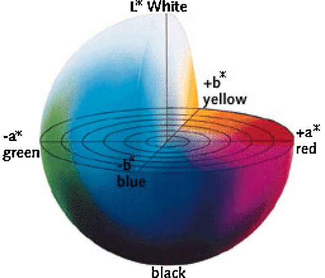
Later, in 1976, as digital imaging was starting to become more popular, a variant to the chromaticity diagram was introduced that better accounted for ‘lightness’. This is the L*a*b* color model shown in Figure 5. In this context, the term ‘lightness’ (sometimes called ‘brightness’) refers to the amount of light the color reflects or transmits. Just as in actual human perception, the relations between L*, a*, and b* are nonlinear, more closely approximating the reality of the image than other conventional techniques. However, the color gamut is so large it wasn’t until recently that L*a*b* became commonplace in digital imaging applications like Adobe Photoshop since digital storage and processing power are no longer limiting factors for digital imaging.
Measurement Techniques for Colorimetry
There are three basic measurement configurations for colorimetry: emission, transmission, and reflection.
Emission
Emission is the simplest of the three and is generally only utilized in colorimetry for lighting and display applications. For these applications, two standard measurement configurations are used, depending on whether the goal is to measure an individual point on a display or the total light at a given point in the room.
To measure different points on display, a configuration commonly referred to as a ‘spot meter’ is used. With this configuration, a collimating lens, as shown in Figure 6 is coupled to a spectrometer via a fiber-optic patch cord. The collimating lens allows for the field of view to be limited to specific locations on display, and assuming the spectrometer has been irradiance calibrated, the x and y values can be calculated by applying the standard observer color-matching functions. These devices are commonly used for color-calibrated displays and monitors used by graphic designers to ensure that the images on their monitors accurately display an image as it will appear when printed.
Conversely, if the goal is to measure the total light incident on an object, then instead of using a collimating lens, a cosine corrector (also shown in Figure 6) is used instead. This allows light to be collected over a 180-degree field of view, or, more accurately, a 2p steradian solid angle. This collection geometry allows for the total light incident on the object to be analyzed, providing an accurate measurement of the chromaticity at the location of interest. This configuration is known as a ‘spectral irradiance meter’, and they are commonly used in the design of commercial and theatrical lighting, where precise illumination is necessary to convey the desired aesthetic.


Figure 6: Avantes CC-VIS/NIR cosine corrector and COL-UV/VIS collimating lens
Transmission
Many analytical and industrial applications, especially in the realm of food/beverage testing and plastic and glass manufacturing, require colorimetric testing of semi-transparent objects. For these types of colorimetry applications, it is vital to use a highly stable broadband light source such as the AvaLight-HAL, which can be fiber coupled to either a cuvette holder for liquid samples or a variable collimating lens holder (as shown in Figure 5) for larger objects such as transparent plastics and glasses. The transmitted light can then be collected by a spectrometer such as the AvaSpec-ULS2048CL-EVO or for objects which are far more absorbent, the AvaSpec-ULS2048x64TEC-EVO with built-in thermoelectric cooling would be chosen to significantly reduce the dark noise in the detector, allowing for much longer integration times.

Reflection
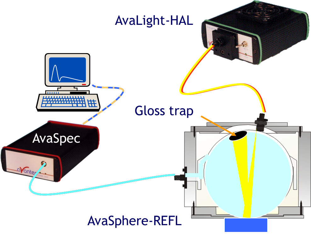
The most common colorimetry measurement technique, especially in the paint industry, is to use reflection to quantitate the color of an object. This process is not only used for quality control in industrial painting and printing but it is used daily in paint stores around the world whenever someone wants to color-match paint to a sample. Reflection measurements are commonly conducted in two different ways, either by using a reflectance probe, as shown in Figure 8 or with an integrating sphere, as shown in Figure 9.
While there are many advantages and disadvantages to each of these set-ups, generally, the use of an integrating sphere is deemed to be the most accurate because it isn’t subject to alignment variations. Additionally, when using a traditional 45/0-degree probe geometry, the specular component is not collected for a flat object but may be collected to varying degrees for objects with an irregular surface structure. If this technique is used for quality control in cases where samples have the same structure, probes can provide repeatable data, making this configuration ideal for industrial inspection applications.
When using an integrating sphere with a typical eight-degree incident angle – often referred to as a ‘D8 geometry’ – the surface variability is eliminated because the light is diffused by the integrating sphere, providing a much more repeatable measurement. Additionally, an integrating sphere can be configured with or without a ‘gloss trap’, which can allow the specular reflection to either be collected or eliminated. While only the diffuse component of the reflected light contains the ‘pure’ color, the specular component will include the surface’s ‘glare’, which can affect how the color will be perceived, so it is often beneficial to take a measurement both with and without specular reflection included.

Color Measurement Video
Final Thoughts
While this application note is by no means a comprehensive review of all of the colorimetry and color science, it provides an introductory overview of the science behind both color perception and color quantitation. Additionally, we have demonstrated the three main techniques for colorimetric measurements with examples that should provide the framework necessary to determine which set-up is needed for a particular application. It is also important to note that while this application note primarily focused on the use of configurable ‘lab set-ups’, this was only done for simplification. All of the measurement set-ups explained in the application can also be integrated into an industrial instrumentation installation; for example, the AvaSpec-Mini is an ideal OEM spectrometer option for integration into colorimetric instrumentation.
For more information on colorimetry and about the full range of OEM spectrometer options available from Avantes, please feel free to contact us. Our knowledgeable application specialists are available to assist you.
Related Products
Related Pages
Resources
Chimenti, Robert V. ‘Fundamentals of Color Science.’ Optics & Light Lecture, Rowan University, Glassboro, NJ, November 2018.